 |
|
 |
|

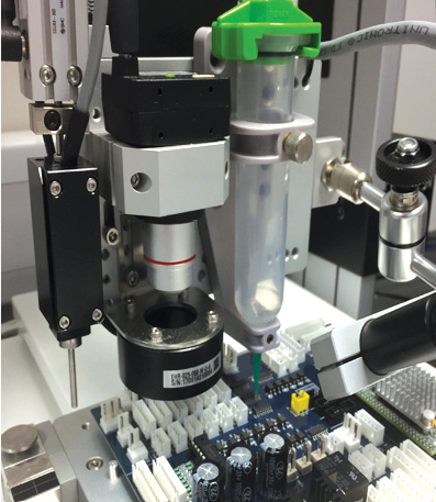
A powerful and intelligent CCD vision programming and auto adjustment system for creating both simple and complex dispense routines. This results in improved quality due to precise dispense positioning alongside improved production yield and reduced processing time and costs.
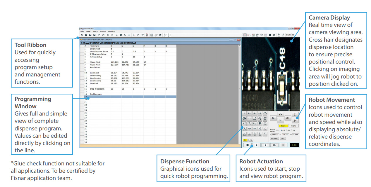
Dispense programs are created quickly and easily in the Fisnar proprietary vision-controlled Fluid-In-Motion (FIM) software by using the displayed camera image to jog the robot to the exact required dispense location, and then selecting the operation wished to be carried out (dispense dot, line start etc).
Vision System software is supplied with an auto-part alignment function to guarantee fluid is being dispensed at the exact required location. This is achieved by the system capturing an image of two separate fiducial locations on the component and using pattern recognition software to compare the live image against a stored image. Any difference found in X or Y position results in the dispense coordinates being automatically adjusted to suit.
Dispense positional accuracy and repeatability is further optimised by the simple auto-calibration routine and part alignment function.
| Item Number | |
|---|---|
| F4000AKIT-VISION | Request a QuoteRequest a Quote |
For simple user setup, programming, and operation.
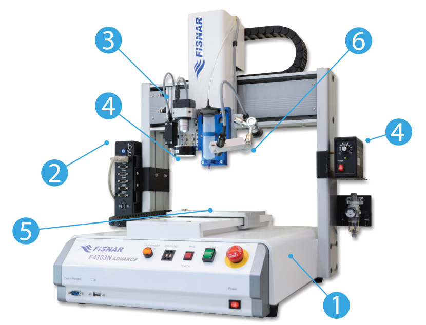
Highly robust and durable based on their cast aluminium base and heavy duty extruded aluminium twin vertical side pillars supporting the horizontal X-axis. This rigid design concept allows for long term precision dispensing and dependable repeatability.
Industrial specification PC installed with Windows 7 and supplied installed with Fluid-In-Motion (FIM) software ready to use. Unit mounted directly onto robot to reduce overall space envelope. TFT LCD monitor, keyboard & mouse included.
For high resolution color and grayscale image capturing.
For optimising image contrast and definition. Adjustable light brightness controller is mounted directly onto the robot to reduce the overall space envelope.
Works by the camera capturing an image of the purged fluid and uses pattern recognition to compare it against a pre-defined datum image. Any difference found between the center positions result in the X and Y coordinate values being automatically adjusted and dispense program re-aligning to suit. The Z-axis is automatically calibrated by the dispense tip contacting a touch pad.
Displays a live image on the TFT LCD monitor allowing the user to clearly monitor the fluid being dispensed onto the component part while a dispense cycle is taking place.